click and draw rotating 3d file
Module 8: Rotating 3D Models
When you have completed this module, y'all will be able to:
- Apply the TRIM and EXTEND commands when trimming and extending in three dimensional wireframe modeling.
- Apply the ROTATE3D command to rotate 3D models.
Rotating in 3D
AutoCAD has private 2D and 3D rotate commands. The 2D rotate command is ROTATE and in 3D, it is ROTATE3D. In this module, using the ROTATE3D command will be taught. It is used to rotate the model in 3D space. The chief difference between the two commands is that the ROTATE command uses a XY bespeak to rotate around and the ROTATE3D command uses two XYZ points or an axis to rotated around. The ROTATE command can be used while 3D modeling every bit long equally all of the objects being rotated are second objects and located on the current UCS. If 3D objects are going to be rotated in 3D space, the ROTATE3D control must be used. See Figure eight-1.

Rotating 3D Model in 3D Space
The ROTATE3D command is used to rotate objects in 3D space around an axis or 2 XY points.
Shortcut: none
Work ALONG: Rotating Wireframe Models in 3D Space
Stride 1
Using the NEW command, beginning a new drawing using the template: 3D Layout English language.
Step 2
Save and name the drawing: AutoCAD 3D Workalong 08-1.
Pace 3
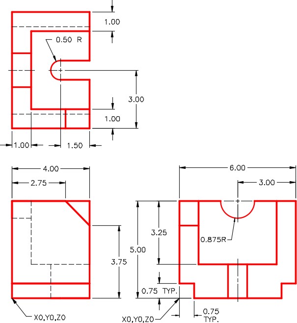
On layer: Model, draw a wireframe model of the object shown in the multiview cartoon. (Effigy Stride 3A and 3B)
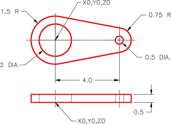
Dimensioned Multiview Drawing
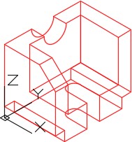
SE Isometric View
Step 4
Enter the commands, as shown below, to set the TRIM and EXTEND commands while working in 3D.
Command: TRIM
Current settings: Project=None, Edge=No Extend
(Note how in this case, the Projection is set up to None and Border to No Extend. Your figurer might exist different.)
Select cut edges … (Select an object, any object)
Select objects or <select all>: (Press Enter)
Select object to trim or shift-select to extend or [Fence/Crossing/Projection/Edge/eRase/Undo]: P
Enter a projection option [None/Ucs/View] <None>: U
(Enter U for Ucs.)
[Fence/Crossing/Project/Edge/eRase/Disengage]: E
Enter an implied edge extension mode [Extend/No extend] <No Extend>: East
(Enter E for Edge and then another for Extend. That means that the intersection of the ii objects that you are trimming or extending do not have to physically intersect. AutoCAD will extend them to find the credible intersection for y'all.)
Control: EXTEND
Electric current settings: Project=Ucs, Edge=Extend
Select cutting edges …
Select objects or <select all>:
(By entering the EXTEND command, y'all volition at present see the settings are set for this command every bit well.)
Command:
Pace 5
Enter the TRIM command equally shown below. The Electric current settings: should be fix as shown. If not, go dorsum and redo Step 4. If they friction match, abort the command.
Command: TRIM
Current settings: Projection=UCS, Border=Extend
Select boundary edges …
Step six
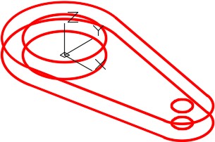
Enter the ROTATE3D, as shown below, to rotate the model 90 degrees counterclockwise around the Ten axis. (Effigy Pace vi)
Command: ROTATE3D
Current positive angle: ANGDIR=counterclockwise ANGBASE=0
Select objects:
Specify opposite corner: 22 institute
(Using a window, select all the objects)
Select objects:
Specify starting time bespeak on centrality or ascertain centrality by [Object/Last/View/Xaxis/Yaxis/Zaxis/2points]: X
(Rotate effectually the 10 axis.)
Specify a betoken on the X axis <0,0,0>:
(Printing Enter to select 0,0,0 equally the base point of the rotation.)
Specify rotation angle or [Reference]: 90
(The bending is positive since looking along the 10 axis towards 0,0,0, counterclockwise is the direction y'all want to rotate.)
Control:
Stride 7
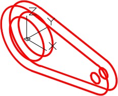
Using what you learned in Stride 6, rotate the model 90 degrees around the Y centrality. This rotation volition have be negative 90 degrees since the rotation is clockwise. (Figure Footstep 7)
Step 8
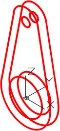
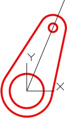
Change the UCS to the front and locate information technology at the center of the circumvolve. (Effigy Pace 8)
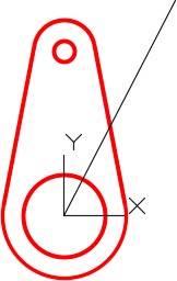
Stride 9
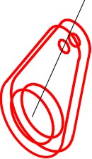
On layer: Construction, draw a line from 0,0,0 at any angle and any length. The line y'all draw does not have to match the figure exactly. Draw it past middle. (Figure step nine)
Step 10
Change to the Front view to ensure that the line was fatigued correctly. (Figure Step 10)
MUST KNOW: The TRIM and EXTEND commands should take the post-obit default settings when working in 3D:
Current settings: Projection=UCS, Edge=Extend
Step xi
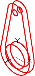
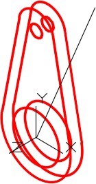
Change the current view to SE Isometric and enter the ROTATE3D command, as shown below, to rotate the model using the Reference option. (Figure Step 11)
Command: ROTATE3D
Current positive angle: ANGDIR=counterclockwise ANGBASE=0
Select objects:
(Select all of the model objects in a window. Exercise not include the reference line that you just drew in the choice.)
Specify opposite corner: 22 institute
Select objects:
Specify beginning point on axis or ascertain axis past
[Object/Final/View/Xaxis/Yaxis/Zaxis/2points]: Z
(Rotating around the Z centrality.)
Specify a point on the Z axis <0,0,0>:
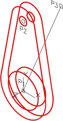
Specify rotation angle or [Reference]: R
Specify the reference angle <0>: (cen) P1
Specify 2d point: (cen) P2
Specify the new angle: (cen) P1
(Annotation that you have to select the P1 location twice.)
Specify second point: (cease) P3
Command:
MUST KNOW: Unlike the ROTATE control where the object is rotated around a point, the ROTATE3D uses ii XYZ points to rotated effectually. You can use the Ten, Y or Z centrality or two endpoints of a line.
Step 12
The wireframe model should at present appear as shown in Effigy Step 12A. Modify the current view to Forepart to ensure that the model was rotated correctly. (Effigy Footstep 12A and 12B)
Step 13
Relieve and shut the cartoon.
USER TIP: When using the ROTATE3D command, ensure that the ANGDIR and ANGBASE system variables are set as shown below. These setting volition display when y'all enter the command, as you can see below. Afterwards yous go more familiar using 3D, you can change these settings. While working on the AutoCAD 3D book, exit them set up as shown.
Command: ROTATE3D
Current positive angle: ANGDIR=counterclockwise ANGBASE=0
Cardinal Principles
- While working in 3D, the TRIM and EXTEND commands should have the post-obit default settings: Project=UCS, Edge=Extend
- The ROTATE command, used for a 2D rotate, uses a XY signal to rotate For a 3D rotate using the ROTATE3D command, ane of the axises, a line or two XYZ points must be specified to rotate effectually.
- To observe whether the 3D rotation direction is counterclockwise or clockwise, wait at 0,0,0 from the positive terminate of the axis you are rotating effectually.
Lab Exercise viii-1
Time allowed: 60 minutes.
| Drawing Name | Template | Units |
|---|---|---|
| AutoCAD 3D Lab 08-1 | 3D Layout English | Inches |
Step 1
Depict all construction objects on layer: Structure and all model objects on layer: Model.
Footstep 2
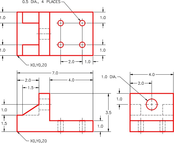
Depict a wireframe model of the object shown in the figure. (Figure Step 2A, 2B, 2C,and 2d)
Stride 3
When complete, freeze layer: Construction.
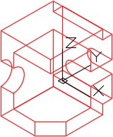
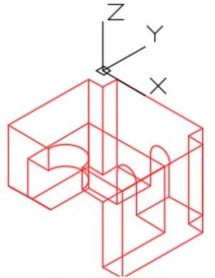
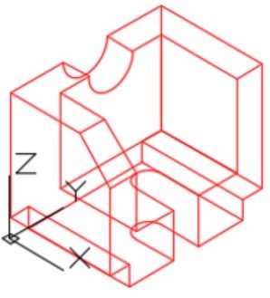
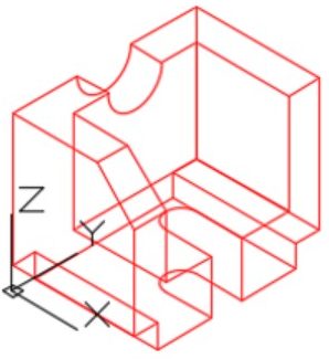
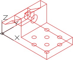
Dimensioned Multiview Drawing
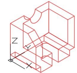
Completed Wireframe Model SE Isometric View
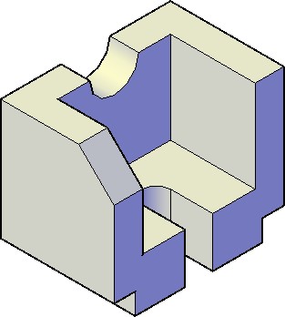
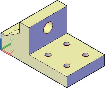
Solid Model – SE Isometric View
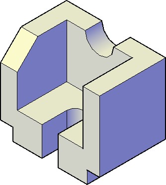
Solid Model – NE Isometric View
Step four
Enter the UNITS command. In the Units dialogue box, set the Insertion Units to Inches. Change the location of the UCS to World and check the model with the key.
Footstep 5
Ensure that the USC is gear up to World and the electric current view is SE Isometric. (Figure Step 5)
Step 6
Rotate the model ninety degrees around the X axis. (Effigy Footstep 6)
Step 7
Rotate the model 90 degrees around the Y axis. (Figure Stride 7)
Step 8
Rotate the model 90 degrees around the X axis. (Figure Stride 8)
Pace ix
Rotate the model 90 degrees around the Z centrality. (Effigy Step ix)
Pace 10
Save and close the drawing.
Lab Exercise viii-2
Time allowed: 40 minutes.
| Drawing Proper name | Template | Units |
|---|---|---|
| AutoCAD 3D Lab 08-2 | 3D Layout English | Inches |
Step 1
Describe all construction objects on layer: Construction and all model objects on layer: Model.
Step two
Describe a wireframe model of the object shown in the effigy. (Figure Footstep 2A, 2B, 2C, and 2D)
Step iii
When complete, freeze layer: Structure.
Dimensioned Multiview Drawing
Completed Wireframe Model SE Isometric View
Solid Model SE Isometric View
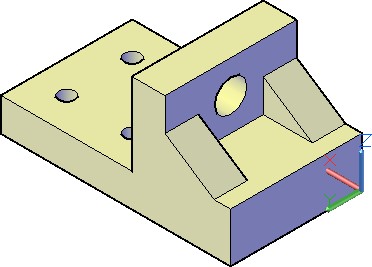
Solid Model NW Isometric View
Step iv
Enter the UNITS command. In the Units dialogue box, fix the Insertion Units to Inches. Change the location of the UCS to Earth and check the model with the key.
Step five
Relieve and close the cartoon.
Source: https://opentextbc.ca/autocad3d/chapter/rotating-3d-models
Belum ada Komentar untuk "click and draw rotating 3d file"
Posting Komentar